 The 65C816 XL/XE OS
revision
The 65C816 XL/XE OS
revision
WDC 65C816S, or shortly 65C816, is a microprocessor designed and produced by Western Design Center. The CPU is a successor of the 6502. Various versions of the 6502 were used in computers like Apple II, Atari 400/800/XL/XE, Commodore C-64, C-128 etc.
The difference between 6502 and 65C816 is that while the former one is a fully 8-bit CPU, the latter one, eventhough it is equipped with 8-bit data path to the memory, has an internal structure that allows 16-bit data processing. 16-bit wide registers, up to 64 kB of the stack, many new addressing modes and instructions (including memory-to-memory moves, unknown to the 6502). And, which is one of the most important things, thanks to the 24-bit address bus the CPU allow you to use 16 MB of directly addressable memory. It can also work with higher frequencies, up to 14 MHz.
All this stuff makes the 65C816 an interesting extension, that we can put into 8-bit Atari. This page discusses some aspects of such an extension.
- I. Preface
- II. User's manual
- III. Interrupt considerations
- IV. New system call mechanism
- V. New SIO functions
- VI. New CIO functions
- VII. The "N:" device
- VIII. The "@:" device
- IX. Memory management
- X. Memory map changes and enhancements
- XI. Other changes
- XII. Compatibility
I. Preface
65C816 has two modes of operation. The first one is 6502 emulation mode. The CPU "wakes up" being in it, to keep the backward compatibility with systems written for 6502. The other one is 65C816 native mode offerring most important extensions, such as 16-bit registers. Unfortunately, the XL/XE ROM must be modified first, if you want to use the native 65C816 mode, for the reasons explained below. This necessity made me think, that it could be worth the effort to prepare not a patched XL/XE OS, but rather something like a new XL/XE OS release, written in 65C816 code, with some long-awaited bugfixes and extensions which seemed necessary, or at least useful.
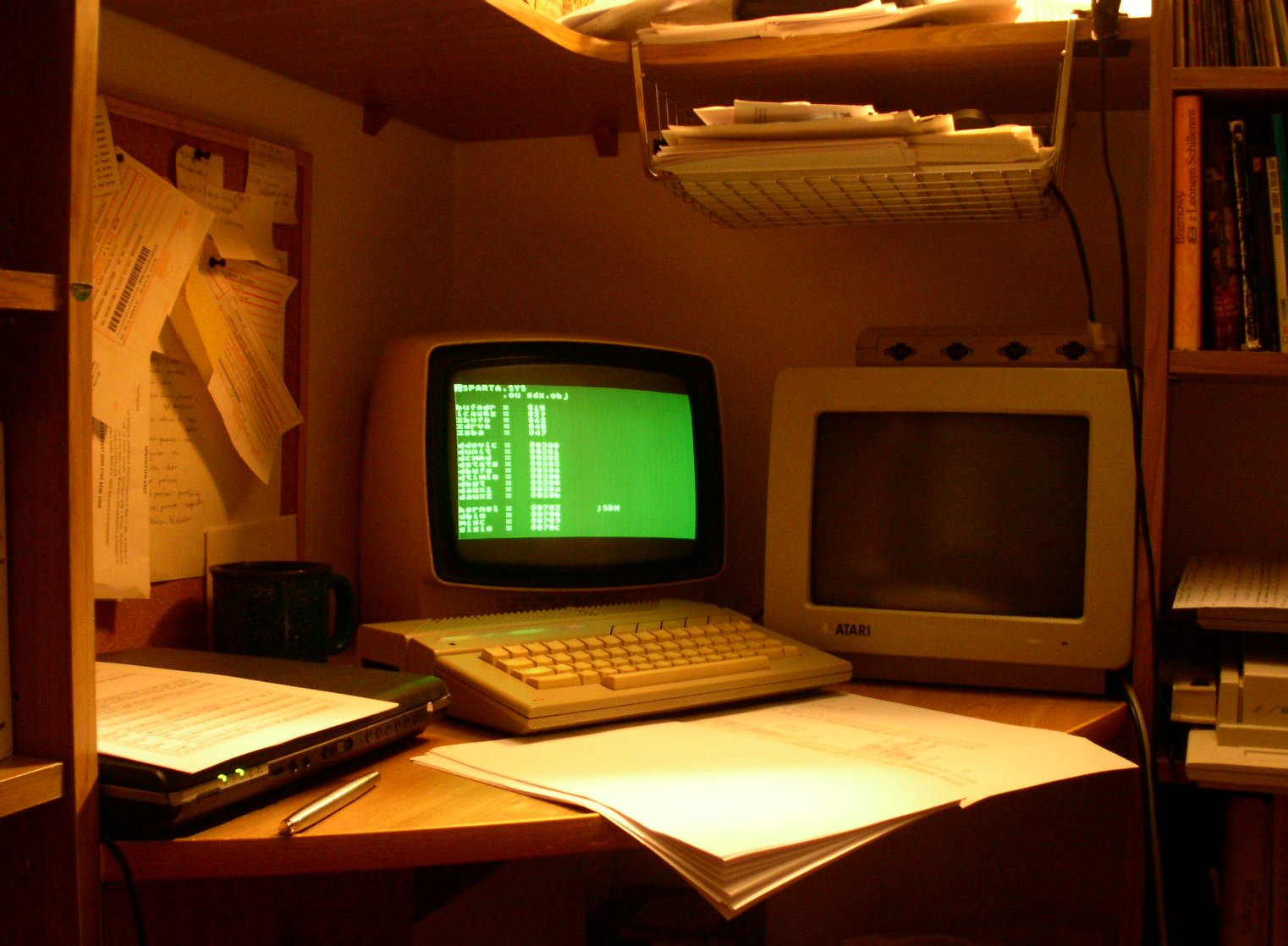
All the works done on the OS I do on my Atari 65XE equipped with 65C816, internal SpartaDOS X, 256 kB XE-compatible RAM, 2,5-inch 2.1 GB hard drive Toshiba MK2103MAV (attached through the KMK/JŻ IDE interface), and of course the ROM described here. The system is written and compiled with MAE 1.2 made by John Harris.
The ROM modification is done to achieve the following things:
- make possible to use the 65C816 native mode on Atari XL/XE computers without problems and with interrupts enabled. The XL/OS rev. B does not contain any sensible values at the place where the 65C816 expects the native interrupt vectors, hence the crashes.
- make the memory mapped at extra addresses ($010000-$FFFFFF) accessible and usable for programs. Running code in this memory requires switching to native mode, and for native mode see above.
- provide some more extra services related to the 65C816 such as new interrupt vectors, basic memory management routines etc.
- develop new system of entry points: current mechanism of making ROM calls is difficult to use, when the code resides above the address $FFFF.
- update the FP routines and make them somehow faster (low priority).
- remove the SelfTest and replace it with something more sensible. Provide extra testing routines too.
- prepare a 65C816-aware, loadable version of Atari BASIC (last).
- possibly expand the printer handler, so that it could be directly used with other printers than Atari printers (low priority).
- fix known bugs.
II. User's manual
They way you use the new system doesn't practically differ from the way you use the XL OS. The only noticeable difference is the function of the console keys:
- the OPTION key, when held down at system start, enables the internal Atari BASIC (under XL OS holding down the OPTION key disables the BASIC).
- the SELECT key, when held down at RESET time, forces cold boot.
- the START key, when held down at system start, invokes a menu, that allows to select boot drive. In XL OS holding down this key causes an attempt to boot from cassette. In the new OS this has been abandoned.
1) Default boot drive
Unlike in the XL OS, the default boot drive number is determined before, and not after the PBI initialization. As a result, the hard drive handler has a possibility to change the boot drive number without doing any tricks, which are necessary under XL OS. The KMK/JŻ interface uses this possibility.
2) Boot menu
The menu allows to select the boot drive number. The selection is done using either cursor keys (up/down arrows) or hitting a key with a letter visible at the left edge of the screen. After each change the computer tries to communicate with the selected drive and prints a brief information about it:

|
- NO RESPONSE - timeout while attempting to communicate with the drive; the drive is probably not attached properly to the computer.
- ULTRA - the drive responded and it is an US Doubler compatible device, fast SIO protocol is enabled.
- XF-551 - the drive responded and it is a CA-2001, Indus GT or LDW 2000 Super (with Synchromesh loaded), or an XF-551, fast SIO protocol is enabled.
- PBI - the drive responded, and it is a parallel device, most probably a hard drive partition.
- no additional information means, that the drive responded and it is a standard disk drive.
If you don't want the turbo mode for a reason, press the "T" key. This toggles the turbo mode off and on for the preselected drive. The drive selection is confirmed with RETURN key. Hitting it causes the menu to be left, and the system initialization continues.
The menu is 100% "E:" device compatible, so it should be visible and working even if an external video device is attached to the computer via the parallel bus interface. I tried to make the menu to be in classic Atari style, so it is stylized after DOS 2.5.
3) Booting
There is also a small, but noticeable difference in the boot procedure. If the default drive is not connected, or if the user has selected a nonexistent drive in the boot menu (this is allowed), the system then tries to find a first bootable drive searching through all possible units. This means, that when there is no drive attached, and no cartridge, that would prevent booting, is inserted either, the boot process takes long time - searching all the drives takes about 30 secs.
4) F1-F4 function keys
The XL OS contains routines to handle function keys F1-F4; there are no such keys on the console, though. There are some hardware solutions allowing you to install and use the keys, such solutions however usually don't take into account the fact, that the routine handling the F1-F4 conflicts with 130XE-style memory expansions. Shortly, pressing some F1-F4 key combinations causes memory banks to be switched in uncontrolled way, and this usually sooner or later results in a system crash.
The reason is that the 1200XL, 1400XL and 1450XLD computers have console LEDs, which signalize certain OS states you can select with F1-F4. These LEDs are controlled by bits of the PORTB register - the same register controls the memory banking in the 130XE computer (and compatibles). The keyboard interrupt routine, when it detects certain F1-F4 key combos, tries to setup the LEDs accordingly, not realizing these do not exist.
This has beed fixed in the new system: using the F1-F4 function keys is safe and doesn't cause any side-effects on computers with memory expansions. At the other hand, on computers without RAM expansions everything will work traditionally - i.e., if there is no 130XE compatible memory, the routine assumes, that the PORTB controls LEDs.
Programming
III. Interrupt considerations
The native interrupt services impose a good deal of problems. Because of the lack of free ROM space, we basically have to put things together so that the same interrupt routines serve for both native and emulation modes.
We presume that:
- all interrupts execute in bank 0 (both code and data); the interrupt routine resets the DBR register and restores it upon exit.
- all interrupts operate on the "real" zero-page ($0000-$00FF); the interrupt routine resets the D register and restores it upon exit.
- all interrupts operate on user stack; the interrupt routine does not realloc itself to the system stack.
- all system interrupt routines must be perfectly executable in emulation mode.
- no system interrupt routine switches ever from native mode to emulation or backwards.
- the same return code may be used for both native and emulation routines (this is even a must for NMI->SYSVBL->EXITVBL sequence).
Disadvantages:
- big interrupt overhead in the native mode; the CPU state must be accurately saved no matter what, and the 65C816 has much more registers and much more processing states than 6502. In the case of DLI the registers do not have to be saved, but the service routine must be executed in some predefined state. This takes a lot of cycles too.
- slower interrupt processing for the 8-bit code is used.
Advantages:
- no double interrupt service routines - we're short of ROM space!
- stable interrupt overhead in the user selected CPU mode: the OS does not switch emulation/native modes beyond the user control (except for system call).
- the user can employ the same interrupt routines for both modes.
At the other hand, the interrupt overhead is reduced in the emulation mode thanks to new instructions and addressing modes. For example, the NMI serivce routine, which takes 32 cycles on 6502, is shortened to 26 cycles on 65C816. Similarly the EXITVBL routine is reduced from 23 to 19 cycles, and other savings take place inside the actual SYSVBL. All this does not balance the increased interrupt overhead in the native mode, reduces it however.
DLI considerations
The DLI is somehow a special case, because this interrupt is extremely time-critical. According to some sources, there are only 104 CPU cycles per one ANTIC scanline, and thus such an overhead as 94 cycles - the "save everything" option - is not acceptable.
Because of that the DLI service routine is entered with the CPU state mostly being undetermined. The PBR and DBR are set to 0, and the accumulator size is 8 bits. Nothing else is known or saved. The routine must be ended with RTI, the OS will restore the DBR for you.
Notice: the accumulator is not saved, you have to save it before use (with PHA) and restore before RTI. Notice that if you want to use the full 16-bit accumulator, your code won't work in emulation mode.
Notice: the X/Y registers are not saved. Moreover, their size is unknown. Remember, that if you're gonna use them, you must save their values first with PHX and PHY respectively, and then determine the required size. Consider the following examples:
; Example 1
; Use of the X register, size 8-bits.
; Note that you have to save them BOTH, even if
; you use ONLY ONE of them as 8-bit size register!!!

	rep #$10	;set both registers to 16 bit
	phx		;you must save them BOTH before switching to 8-bit
	phy
	sep #$10	;switch to 8-bits
	...
	your code here
	...
	rep #$10	;switch back to full size
	ply
	plx
	rti
The reason for switching X/Y to 16-bit before setting to 8-bit is that the register size is not determined while the DLI service routine is being entered (see above). Omitting the REP instructions would save 10 cycles, if the registers are already set to 8-bit size (2*3 cycles for two REPs, and 4*1 cycles for pulls and pushes); but if they're NOT 8-bit, the PLY/PLX instructions at the end will pull wrong number of bytes from the stack causing your program to crash.
; Example 2
; Use of the X register only, size 16-bits.
; In this case you only save the registers
; which you use. Notice that this code won't
; work in emulation mode.

	rep #$10
	phx
	...
	your code here
	...
	plx
	rti
Similarly, if you want to use zero page registers, you most probably will have first to save and reset the D register value. This is done so:
; Example 3

	phd		;save the D register
	pea $0000	;reset it
	pld
	...
	your code here
	...
	pld
	rti

; Example 4
; This gains 5 cycles, if you use 16-bit accumulator
; for other purposes too.

	rep #$20	;16-bit accumulator
	pha
	phd
	lda #$0000
	tcd
	...
	your code here
	...
	pld
	pla
	rti
However, saving, resetting and restoring the D register is avoidable if:
- your interrupt routine does not use zero page locations;
- your interrupt routine accesses zero page using absolute or long absolute addressing mode;
- your program reallocates zero page and the interrupt routine uses locations only on this private zero page;
That last approach is probably most profiteous, as long as we don't have multitasking.
VBL considerations
In the native mode, the VBL routine is entered with D=0, DBR=0 and PBR=0. All registers are saved except for the MSB of the accumulator: if you're going to use 16-bit accumulator or the XBA instruction in your VBL routine, you must first push the entire 16-bit accumulator to the stack and pull it before exit.
The top of the stack looks identical in both native and emulation modes: the 8-bit Y register is the topmost, then below go 8-bit X register and 8-bit accumulator, the P register, and 16-bit return address.
However, in the native mode there are additional data yet below, such as 24-bit return address, additional register values etc. Everything this is pulled *AFTER* the EXITVBL routine is executed.
IRQ considerations
In the native mode, the IRQ routine is entered with D=0, DBR=0 and PBR=0. All registers are saved except for the MSB of the accumulator: if you're going to use 16-bit accumulator or the XBA instruction in your IRQ service routine, you must first push the entire 16-bit accumulator to the stack and pull it before exit.
The top of the stack looks identical in both native and emulation modes: the P register is the topmost, then below goes the 16-bit return address.
However, in the native mode there are additional data yet below, such as 24-bit return address, additional register values etc. Everything this is pulled *AFTER* the RTI is executed.
Exact interrupt overhead
Exact interrupt overhead, in cycles, in comparison to XL OS. The NMI overhead is calculated from the NMI signal to the moment, when the first user instruction (pointed to by DLIV and VVBLKI) is fetched by the CPU; and from RTI completion to the actual return from interrupt.
The IRQ overhead is calculated from the IRQ signal to the moment when the interrupt source recognition routine (SINRDYI) is reached; and from RTI completion to the actual return from interrupt.
| XL OS | Emulation mode | Native mode | |
| DLI | 18/0 | 18/0 | 48/12 |
| VBL | 38/0 | 32/0 | 98/30 |
| IRQ | 14/0 | 12/0 | 63/30 |
Note that in native mode both interrupt and RTI each take 1 cycle longer, and this time is already added here.
Also note, that both NMI and IRQ interrupts have own master vectors in RAM, which are jumped through first, before the system routines are executed. This adds 6 cycles to the overhead, and this time is already taken into account here (if such vectors existed in XL OS, the XL OS interrupt overheads would be 23, 42 and 19 cycles for DLI, VBL and IRQ respectively).
IV. New system call mechanism
The old system call mechanism present in the XL OS, based on a jump table and JSR calls, has a limitation that makes its usage problematic with new, 65C816 programs, which can possibly store the code beyond the 64k boundary.
Namely, the JSR instruction has a 16-bit argument, and thus cannot cross the 64k bank boundary. As a result, when you make a JSR $E459 call while your program is executing in the bank 0 (and on 6502 this is always the case), the call will reach its destination, i.e. the $00E459, where the actual ROM procedure resides. However, doing the same in bank 1 makes the call go to $01E459, which is not the place where it should actually find itself.
At the other hand, the 65C816 offers a JSL call, jump to subroutine long, which accepts 24-bit address as an argument and stores a 24-bit return address on the stack. However, the ROM routines expect a 16-bit return address to be stored, and we have to keep this behaviour to maintain compatibility with older programs. Thus, the JSL instruction cannot be used to call the system.
Providing an alternative jump table (for long calls) would solve the problem, but first of all it would be a great waste of ROM space. Not to mention the fact, that the jumptable metod is not considered very flexible, as you can never change the vectors which are in ROM, thus you can't patch the OS with software, when necessary.
The new calling method
The new calling method is based on the COP instruction handler. COP generates an unmaskable software interrupt, quite similar to the TRAP instruction on the Motorola 68k. The COP accepts a constant (immediate) argument. The instructions with the arguments of the value from $80 to $FF are reserved by the WDC for future usage, possibly for new instructions. The rest, i.e. the range from $00 to $7f, is available for our definition.
The new OS vectors in RAM
The COP handler residing in ROM defines five new vectors in the memory. Most of them are 24-bit long. These are:
VCOPE $000251-$000252 WORD
VCOPN $000256-$000258 LONG
Two COP interrupt vectors, for the emulation and native mode respectively. The first is not used by OS for now, it simply points to the RTI instruction. The reason for that is, that being in emulation mode you do not really need the new calling mechanism, you may happily use the old one, as you cannot run code outside the first 64k anyways.
The other vector, VCOPN, points to the system handler. If you change this vector, you must end your code with a JMP to the old location, or RTI if you bypass the ROM completely.
VCOP0 $000262-$000264 LONG
VCOPU $000265-$000267 LONG
VCOPC $000268-$00026a LONG
These are secondary vectors jumped through by the system handler (the one pointed to by VCOPN). The code pointed to by them is called with a JSL instruction and must be ended with RTL (or a JMP to the old location).
The first vector is called, when a COP #$00 is executed. This instruction is reserved for the usage of the operating system, details below.
The second vector is called when any COP instruction with an argument range $01-$7F is executed. The third vector is called when the reserved COP instructions are executed (i.e. argument range $80-$FF).
The long vector at $000018 points to the argument of the instruction that caused the call (i.e. if COP #$00 was executed, the vector points to the "#$00" part of the instruction).
All the secondary vectors are called in native mode, with D=0, PBR=0, DBR=0, and with 16-bit register sizes. The contents of the CPU registers is unmodified and should be the same as when the COP interrupt occurred (except for VCOP0, where registers reflect the content returned by OS). The handler residing at the primary vector (VCOPN) is responsible upon exiting for restoring the CPU context to the state being actual prior to the call.
Special meaning of the COP #$00 instruction
The COP #$00 instruction has been defined as a system emulation interrupt. The ROM handler residing behind it accepts a 16-bit address pointing to a location within the bank 0 (first 64k), calls it with a JSR instruction, and returns the results of the call to you. Upon exit, the registers contain values returned by the OS. The P register bits returned by OS are preserved except for bits M and X, which are restored to the state prior to the call.
Here's an example of a system call using new calling method:
	sep #$30	;set 8-bit registers
	ldx #$10	;select IOCB #1
	lda #$0c	;command: CLOSE
	sta >iccmd,x	;store
	pea jciomain	;push the OS function address
	cop #$00	;call the OS
	pla		;pop the argument off the stack
	pla
Notice that this is the only safe method when calling the system in native mode.
If you use the traditional method, you ought to call the system in emulation mode *only*. Even if the OS itself should work perfectly in both native and emulation modes, I take no responsibility for externally loaded device drivers (especially DOS-es), which can contain code that is not compatible with the native mode.
V. New SIO functions
The availability of most functions is indicated in the @:SYSDEF file. Relying on ROM version number is not a good idea - all stuff explained below about version numbers has informative character only.
As of ROM version BB 02.08 the SIO is able to read data (e.g. disk sectors) directly to the high-memory past the first 64k, and to write data from that area. The DCB has been extended to 16 bytes, the most significant byte of the 24-bit address is located at $00030E.
However, for backward compatibility with old software, and, first of all, with existing parallel bus devices, setting a 24-bit address in the extended DCB won't have any effect. This is so because a device designed to do I/O within 16-bit address space may not understand 24-bit addresses, and thus the data would be stored to (or fetched from) improper memory location. There must exist an additional mechanism that prevents this.
For this purpose, three new virtual devices have been defined inside SIO; the codes are as follows:
- $B1 (= $31 + $80) - disk
- $C0 (= $40 + $80) - printer
- $D0 (= $50 + $80) - RS-232C
Calling SIO with such a code in DDEVIC tells the SIO handler to take the full 24-bit address from the DCB, and that the upmost byte of this address is at $00030E (the SIO assumes otherwise, that the upmost byte of this address is 0). Except that virtual devices operate identically to the traditional $31, $40 and $50; and the virtual device code is translated to the real one before sending out the command via the serial port.
Accepting the command the SIO does not check or prove in any way, that the extended memory exists. It is assumed, that the program knows already, that the memory exists, before it requests a read/write operation on this memory; it can do that e.g. with the memory management functions.
VI. New CIO functions
1.
As of version BB 02.03 the CIO now accepts 0 (zero) as device's unit number, for example such a name as "D0:" will be decoded as "device D:, unit 0". In previous versions of the system such a number was silently changed to unit 1. Notice, that this extension is backported from the system developed in Atari Inc. for the 1450XLD computer.
2.
As of version BB 02.05 the ROM-contained CIO interface features a new function: it can now automatically search the IOCB channels for a free (closed) one. A call like this:
	ldx #-1
	jsr jciomain
will return status in the Y register (1 - success, or a negative error code otherwise), and the channel number multiplied with 16 in the X register.
3.
As of version BB 02.08 the ROM-contained "K:" handler features four XIO functions as follows:
- XIO 16,#1,4,0,"K:" - disables the keyboard click
- XIO 16,#1,4,1,"K:" - enables the keyboard click
- XIO 16,#1,4,255,"K:" - returns (in ICAX3) information about keyboard click state (0 - disabled)
- XIO 19,#1,4,0,"K:" - generates a single keyclick, if enabled, and does nothing otherwise
4.
As of version BB 02.08 the ROM-contained "K:" handler features new "scanning" mode of operation. In this mode, when you call the GET function of the keyboard, and no data is available (= the user did not press any key), the function does not block and busy wait for data availability, but returns immediately instead.
The function gets activated for a particular stream by opening it for keyboard with bit 0 of ICAX2 set to 1, for example:
OPEN #1,4,1,"K:"
After that, any GET #1 returns status 1 in Y register and the ASCII code of the key only if a key was pressed. If no key was pressed, the function returns status code -78 (178, $B2), and the accumulator value is meaningless.
Enabling this mode for a "K:" channel does not affect other channels and does not affect the console device ("E:") either.
Unfortunately, this mode cannot be easily used with BASIC, because the status -78 is considered an error by the BASIC interpreter, and it aborts program execution.
VII. The "N:" device
As of version 1.93 the ROM contains handler for a new device - "N:" (null). It works as follows:
- while reading from it, it can behave in three different ways depending on the name given while opening: "N:", "N2:" or "N3:"; see the table below.
- while writing to it, it accepts any number of data and doesn't store the data anywhere (the data stream is sent to nowhere-land).
- there are no special operations.
| Name | Function |
| "N:"or"N1:" | When reading, the device behaves like a zero-length file: on any GET operations status -120 (136, EOF) is returned. This mimics the behaviour of the Unix' /dev/null |
| "N2:" | When reading, the device behaves like a file of an infinite length containing zeros. This mimics the behaviour of the Unix' /dev/zero. |
| "N3:" | When reading, the device behaves like a file of an infinite length containing random data. This mimics the behaviour of the Unix' /dev/random |
VIII. The "@:" device
"@:" is a pseudo-disk which contains only one file named "SYSDEF". This file's length is 128 bytes. The file contains some information to be used by programs which would like to know f.e. if it is safe to switch into 65C816 native mode.
The "@:SYSDEF" contents is as follows:
| Byte | Contents | ||||||||||||||||||||||||||||||||||
| 0-2 | System revision date: day, month, two last digits of the year number ($04 $06 $23 = 4 VI 2023 - BCD encoding) | ||||||||||||||||||||||||||||||||||
| 3 | Option (0) | ||||||||||||||||||||||||||||||||||
| 4-9 | System version number ($44 $44 $00 $00 $02 $2D = DD 000002.45 - binary encoding) | ||||||||||||||||||||||||||||||||||
| 10 | CPU code (0 - 6502, 1 - 65C02, 2 - 65C816). Codes below 2 are defined just in case someone would have an idea of implementing this on the standard Atari. | ||||||||||||||||||||||||||||||||||
| 11 | Reserved for FPU code (for now 0 - no FPU) | ||||||||||||||||||||||||||||||||||
| 12 | Number of additional 64k banks | ||||||||||||||||||||||||||||||||||
| 13 | Native interrupt services: * bit 0 = 1 - available If the tenth byte is 2, and this byte is 0, then you cannot switch to 65C816 native mode with interrupts on. | ||||||||||||||||||||||||||||||||||
| 14 | Memory (kmemory) management availability: * bit 0 = 1 - available This field and following ones are valid as of version BB 02.05 of the ROM. | ||||||||||||||||||||||||||||||||||
| 15 | SIO extensions: * bit 0 = 1 - extended DCB (16 bytes) * bit 1 = 1 - SIO can read/write data to/from high mem | ||||||||||||||||||||||||||||||||||
| 16 | Fast serial I/O for disk drives: * bit 0 = 1 - US Doubler * bit 1 = 1 - XF-551/Indus GT | ||||||||||||||||||||||||||||||||||
| 17 | CIO extensions: * bit 0 = 1 - CIO channel lookup function availability available | ||||||||||||||||||||||||||||||||||
| 18 | Maximum IOCB number multiplied by 16 ($70) | ||||||||||||||||||||||||||||||||||
| 19-20 | A bitmap containing information about XIO functions
for the ROM-contained "E:" handler. All bits, starting from 0, mark
function availability for XIO 16 and following ones up to XIO 31.
| ||||||||||||||||||||||||||||||||||
| 21-22 | Same for S: | ||||||||||||||||||||||||||||||||||
| 23-24 | Same for K: | ||||||||||||||||||||||||||||||||||
| 25-26 | Same for P: | ||||||||||||||||||||||||||||||||||
| 27-28 | Same for N: | ||||||||||||||||||||||||||||||||||
| 29-30 | Same for @: | ||||||||||||||||||||||||||||||||||
| 31-32 | Reserved |
If there's no such device or no such file (error 138, 170 or similar while opening "@:SYSDEF"), bytes 10-127 shall be assumed to be zero.
The remaining bytes are for now reserved and are read as zeros.
You can set the read position inside this file using XIO 37 operating similarly as in SpartaDOS X (this function is mandatory for the "@:" device). Setting the value beyond the EOF causes errors at subsequent reads.
IX. Memory management
As of version 02.04 the system defines four memory management functions, comprising a subsystem called shortly "kmem", which stands for "kernel memory manager". The first one - called kpsize - is explained below. The second's one - kmalloc - purpose is to allocate memory blocks, the third one - kfree - to release them.
If it was C, the function prototypes would look as follows:
unsigned int kpsize(void);
int kmalloc(int size, unsigned int mode);
int kfree(unsigned int page);
The smallest memory unit known to these functions is a page. The size of this page - in bytes - is returned by the kpsize() function. Current implementation will return 256 here, and this is quite small amount, considering page sizes on larger systems; for example m68k systems use 8192 or even 16384 bytes per page.
Thus, the kmalloc()'s size argument is not a number of bytes to allocate, but a number of pages. The returned value is not an address of the allocated block either, but rather a number of the page boundary where the block starts. Similarly, such a page number must be given to the kfree() function as its page argument. In current implementation - where a page consists of 256 bytes - the page number is equal to the two highest bytes of the full, 24-bit address of the allocated memory block.
If we pass -1 (or $FFFF) to the kmalloc() as its size parameter, it won't allocate anything, but it will calculate and return the actual number of free pages instead.
Such memory management costs per-block memory losses (upto 255 bytes per allocated block), but its main advantage is that the address fits in 16 bits; this in turn makes passing parameters and receiving results easier, not to mention the function's internal operation; this also simplifies and shortens the global memory map.
Speaking of the map, it currently contains 64 slots (or 42 slots in older versions of the OS). This means, that the system can dynamically manage 64 independent blocks of memory, any number of pages each. If a program would want to allocate 32 kB (128 pages) calling kmalloc() 128 times, it will 64 times succeed, but the 65th time will fail with "Out of memory" error, despite the fact that only 16 kB have been allocated! Thus, the kmalloc() has to be used sparingly: in this example the best approach would be to alloc the entire 32k at one time - id est, with one kmalloc() call.
The mode argument of the kmalloc() modifies its operation according to current requirements. It is a 16 bit word, each bit being a flag switching internal kmalloc() functions on and off. Currently the following bits are defined:
| Bit | Label | Description |
| 0 | KM_RES | If this bit is set, then the memory block becomes "resident" - kfree() doesn't deallocate it. It will be deallocated at warm reset. |
| 1 | KM_RPR | If this bit is set, and the KM_RES is set, then the memory block becomes "RESET proof": nothing except cold reboot will deallocate it. |
| 2 | KM_A64 | Setting this bit tells kmalloc() to alloc memory block not at the first free place, but at the first free 64k boundary. |
| 3 | KM_EXE | Setting this bit means that the memory is allocated for code. A block smaller than 64k must entirely fit within a 64k segment. Bigger blocks are automatically 64k-aligned. |
| 7 | KM_CLR | Setting this bit causes the memory block to be zeroed out. |
The remaining bits are reserved and should be kept zeros for upward compatibility.
The kfree() function accepts the kmalloc()-returned page number as an argument. If there's an allocated and non-resident memory block, it will be deallocated.
The functions explained above are called with COP #$01 instruction, passing arguments on the stack:
        rep #$30
        pea $0000       ;mode
        pea $0100       ;size (256 pages = 64k)
        pea $0001       ;kmalloc() function code
        cop #$01
        plx             ;remove arguments
        plx
        plx
The function returns status (error code) in the Y register. If it contains a positive value, the accumulator contains then the number of the first page belonging to the allocated memory block (the page number, or two higher bytes of its address). If the Y contains a negative value, then an error has occurred and the accumulator contents is meaningless.
Other functions are used similarly, except that kpsize() doesn't expect any arguments. The function codes are as follows:
- $0000 - kpsize
- $0001 - kmalloc
- $0002 - kfree
The rest of function codes for COP #$01 is for now reserved. Calling them returns error -110 (in older OS revisions the $0003 was assigned to a function, which was removed as of version 2.12).
CAUTION: All kmem functions work (1) only in the native mode, (2) only in the memory above the address 65535 and (3) only when this memory does exist. Emulation mode calls have no effect (the COP handler does exist, but consists of loading an error code to Y, and RTI). When no additional memory exists, all functions return negative error code in the Y register.
X. Memory map changes and enhancements
| Address | Size | Label | Description |
| $00024D | BYTE | LOSEGM | Holds the highest byte of the 24-bit address of the first physically available RAM segment past the first 64k. |
| $00024E | BYTE | HISEGM | This is a byte that holds information about the actual number of additional 64k memory segments present physically past the first 64k. A value of 0 means that no additional memory is available. A value of $FF means that the RAM is available at the full addressing space of 16 MB. |
| $00024F $000253 | WORD LONG | VABTE VABTN |
Vectors for the ABORT interrupt in emulation and native mode respectively. Both currently point to an RTI. |
| $000251 $000256 | WORD LONG | VCOPE VCOPN |
Two COP interrupt vectors, for the emulation and native mode respectively. The VCOPE is not used by OS for now, it simply points to the RTI instruction. The other vector, VCOPN, points to the system handler, that dispatches the COP calls and vectors them through VCOP0, VCOPU or VCOPC. If you change this vector, you must end your code with a JMP to the old location, or RTI if you bypass the ROM completely. |
| $000259 | LONG | VNMIN | The master NMI vector for native mode. It is jumped through first, whenever a VBL or DLI interrupt occurs in native mode. By default, the vector points to the system routine that handles both interrupts. |
| $00025C | LONG | VIRQN | The master IRQ vector for native mode. It is jumped through first, whenever an IRQ occurs in native mode. By default, the vector points to the system routine that dispatches the IRQs. |
| $00025F | LONG | VBRKN | The master BRK vector for native mode. It is jumped through first, whenever a BRK instruction is executed in native mode. By default, the vector points to an RTI. |
| $000262 | LONG | VCOP0 | This is the secondary vector for COP #$00 interrupts. It is called with JSL instruction. The vector currently points to system routine which dispatches the system emulation calls. The VTEMP $000018-$1a points to the COP argument when this vector is called. This information can be used when installing RAM-based extensions to the system handler. The instruction and the vector are reserved for the operating system calls. |
| $000262 $000268 | LONG LONG | VCOPU VCOPC |
The vector VCOPU is called when any COP instruction with an argument range $01-$7F is executed. The vector VCOPC is called when the reserved COP instructions are executed (i.e. argument range $80-$FF). The VTEMP $000018-$1a points to the COP argument when these vectors are called. This information can be used when installing RAM-based extensions to the system handlers. Notice that usage of the COP instruction with argument range $80-$FF is reserved for Western Design Center, the CPU manufacturer. |
| $00029F | BYTE | XMS | A number of additional 16k memory banks available at $4000-$7FFF. |
| $00030C $00030D | BYTE BYTE | DAUX3 DAUX4 |
High word of 32-bit sector number (lo/hi byte, respectively) |
| $00030E $00030F | BYTE BYTE | DBFX1 DBFX2 |
DBFX1 is the high word of 24-bit DCB buffer address. DBFX2 is reserved for now and must be held 0 for upward compatibility. |
| $0003ED | BYTE | NEWINI | Imported from Atari 1450XLD ROM: the beginning of warm reset routine for a handler loaded from parallel device. |
| HMS | STRUCT | MEMTAB | Memory allocation table alias global memory map. The exact location and format vary in invarious versions of the OS. If the high RAM does not exist, the MEMTAB doesn't exist either. |
XI. Other changes
As of version 2.10 the CHARSET 2 has been modified, and the characters assigned to ATASCII codes 125, 126 and 127 changed their shapes. These are console control characters, CLR/HOME, DEL and TAB respectively.
The new shapes are:
- ATASCII 125: tilde (~)
- ATASCII 126: left brace ({)
- ATASCII 127: right brace (})
The characters retain their functions as control codes, and still can not be displayed but in an escape sequence (directly after the ESC character, ATASCII 27).
ATASCII codes unfortunately don't match ASCII codes of these characters (left brace - 123, right brace - 125, tilde - 126). The reason is that the ATASCII 123 in CHARSET 2 is already assigned to an international character, namely the German "A umlaut". To properly transfer a text file containing these characters to a PC, conversion must be done (and it is to be done anyways because of different EOL character codes in ASCII and in ATASCII).
XII. Compatibility
This OS will only work with XL/XE hardware, it is NOT compatible with the Atari 400/800 series (won't even start on such a machine).
From the user point of view there are following changes:
- the SELF TEST is removed
- the cassette recorder handler is removed - you cannot use the cassette recorder as data storage anymore
- a menu has been added to select boot disk; to invoke the menu, you have to hold the START key at boot time;
- holding down the SELECT key and hitting RESET should force cold boot;
- for US Doubler, XF-551 and Indus GT compatible drives fast serial I/O is activated automatically;
- few minor bugs an imperfections of the XL OS have been fixed.
- backported most of the changes and improvements Atari did for the XL OS version 2.03 (the system prepared for the Atari 1450XLD computer).
- the graphic routines, screen editor and interrupt handling have been optimized a bit.
- a possibility to boot from a disk that has 512-byte sectors has been added to the boot routines; also, the boot procedure now actively searches for a boot disk, when the preselected drive is not present.
- a possibility to boot from any drive (despite the D1:) has been added;
- the F1-F4 console keys handling has been fixed so that it won't conflict with 130XE-type RAM extensions.
- the CIO has been expanded with new functions and devices.
- memory allocation routines have been added for memory past the first 64k.
- native 65C816 interrupt handlers have been added.
- added a mechanism that makes posible to call the system using software interrupts.
Simultaneously such things as the international character set (CHARSET2) and the routines that handle the 1090XL module have been preserved, for I consider that these can be useful in some (near) future.
From the programs point of view 100% compatibility is kept for such (and only for such) programs, which use legal system calls via jump table or vector tables. Programs, which use some ROM locations directly, won't work correctly (or won't work at all).
To get such a program to work you have to patch it so that it would use legal calls, thus making it generally more compatible with various Atari ROM's around.
In the XL/XE ROM there were some locations employed only to keep compatibility with old 400/800 programs, which use illegal system calls. I think that it is good occasion to make a cut on this - all such stuff has been removed. If a program wants to run equally well on 400/800 OS, XL/XE OS and this 65C816 ROM, it must use legal system calls only.
A compatibility list is available here.
Have fun
